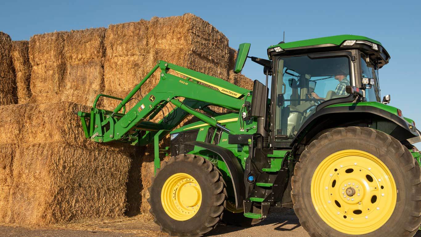
Features
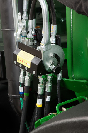 Single-point hydraulic connection
The 700M Loader features a single-point hydraulic connection that saves the operator time when attaching or detaching the loader. This feature also incorporates the connection point for any electrical needs as well as the hydraulic lockout valve. With all hydraulic and electrical connections in one location, installation is quickly completed with the push of a handle.
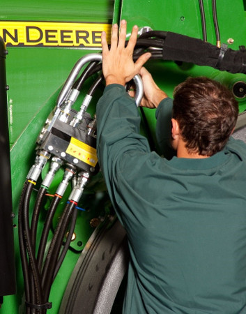 Single-point hydraulic installation
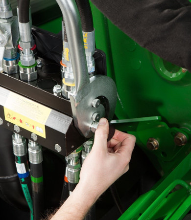 Pressure relief knob
NOTE: Before disconnecting the hydraulic connection between the loader and the tractor, it is necessary to release the hydraulic pressure.
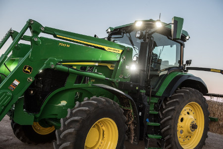 700M Loader with concealed oil lines on 7R 210 Tractor
The 700M Loader has been redesigned to route the oil lines and hydraulic lines through the boom arm and the torque tube. This internal routing ensures better protection of the lines from external damage and improves the overall appearance of the loader.
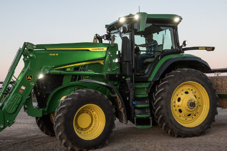 700M Loader on 7R 210 Tractor
John Deere loaders are quickly attached and detached from the tractor without the need for tools. With easy-to-use mast pins, parking stands, and single-point hydraulic connection, the loader can be removed and reinstalled in minutes. To work in applications outside of loader use, John Deere loaders provide an efficient solution to park the loader.
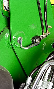 Loader mast pin
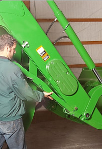 Parking stand
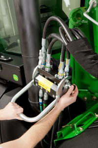 Single-point hydraulic connection
Removal and parking of the loader can be done with the following instructions:
- Apply slight down pressure to the loader boom with the bucket dumped at approximately a 30-degree angle.
- With the tractor in park, install the parking stands and place the mast pins in the open position.
- Utilizing the boom circuit with the tractor in neutral, rotate the mast forward until the mast has rotated past the pin location on the mounting frame by extending the lift cylinder. Using the bucket circuit, rollback the bucket until the mast is removed from the pocket and will clear the tires.
- With the tractor in park, shut the engine off and relieve the hydraulic pressure as indicated for the tractor. Relieve pressure on the single-point hydraulic connection, then disconnect or open the single-point hydraulic connector.
- Store the loader half of the single-point connector on the side of the loader boom. The tractor is now ready to back away from the loader.
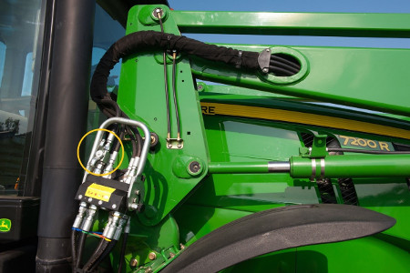 Hydraulic shut-off valve at single-point hydraulic connection
The 700M Loader comes equipped with a hydraulic shut-off valve to improve serviceability. When conducting brief service to the loader, close the hydraulic shut-off to ensure the loader does not move while operating under the equipment. This feature promotes a safe way to conduct brief maintenance without having to use support stands or removing the loader completely.
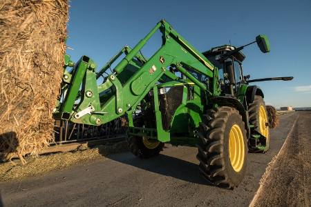 700M Loader working with 7R 210 Tractor
The mechanical self-leveling 700M Loader utilizes a false rod cylinder to improve cycle-time performance. This bucket cylinder is designed with a smaller displacement of oil required on the head end of the cylinder, which allows the cylinder to function more quickly, decreasing operation cycle time. With the false rod cylinder design, loader applications can work more quickly and efficiently.
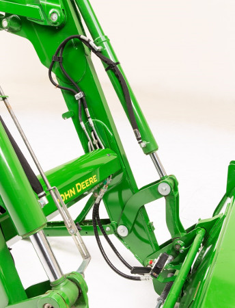 False rod cylinders on 600R Loader
Specs & Compare
Key Specs | 700M Current Model |
| Maximum lift height (A) | 4704 mm 185 in. |
| Lift capacity at full height | Measured at pivot (U) 3310 kg 7282 lb |
| Boom breakout force | Measured at pivot (Y) 4091 kg 9000 lb |
| Bucket rollback force capacity | At ground-level line (ZZ) 4776 kg 10507 lb |
| Clearance at full height - bucket dumped (C) | 3659 mm 144 in. |
| Dump angle, degrees (E) | 70 degree (angle) |
| Rollback angle, degrees (G) | 45 degree (angle) |
Tractor | |
| Model | |
| Front tire | |
| Rear tire | |
| Front axle configuration | |
| Wheelbase | |
| Pump capacity | |
| Rated pressure | |
Loader | |
| Base weight | |
| Leveling configuration | |
| Bucket used | |
| Bucket weight | |
| Lift capacity at full height | Measured at pivot (U) 3310 kg 7282 lb |
| Lift capacity at 59 in. (1500 mm) | |
| Boom breakout force | Measured at pivot (Y) 4091 kg 9000 lb |
| Bucket rollback force capacity | At ground-level line (ZZ) 4776 kg 10507 lb |
| Dimensions | Maximum lift height (A) 4704 mm 185 in. At full height - bucket dumped (C) 3659 mm 144 in. |
| Overall length (I+F), ft (m) | |
| Overall height in carry position (J) | |
| Digging depth (H) | |
| Reach | At maximum height (D) ---- |
| Bucket angle | Dump angle, degrees (E) 70 degree (angle) Rollback angle, degrees (G) 45 degree (angle) |
| Cycle times | |
Additional information | |
Offers & Discounts
Accessories & Attachments
Buckets
 Tractor with heavy-duty bucket with grapple
John Deere heavy-duty buckets for the 700M Loader have holes along the cutting edge where the replaceable and reversible cutting edge can be attached. The holes along the cutting edge provide more than twice the operating life for the cutting edge. This bucket also includes the brackets for attaching the grapple.
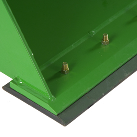 Replaceable wear edge

For loader applications that require frequently scraping the bucket, a replaceable cutting edge will greatly extend the life of the bucket:
- 1850-mm (73-in.) width replaceable cutting edge
- 2150-mm (85-in.) width replaceable cutting edge
- 2450-mm (96-in.) width replaceable cutting edge
- 2750-mm (108-in.) width replaceable cutting edge
 Tractor with heavy-duty bucket with grapple
John Deere heavy-duty buckets for the 700M Loader have holes along the cutting edge where the replaceable and reversible cutting edge can be attached. The holes along the cutting edge provide more than twice the operating life for the cutting edge. This bucket also includes the brackets for attaching the grapple.
 2750-mm (108-in.) high-volume bucket

The high-volume bucket is intended for use with lighter-density, high-volume materials. The bucket capacity makes this an effective tool for handling snow, wood shavings, and other loose materials. The high-volume bucket for the 700M Loader has holes along the cutting edge where the replaceable and reversible cutting edge can be attached. The holes provide more than twice the operating life for the cutting edge.
Hood Guards
 7R 210 Tractor with hood guard
During operation, falling debris and other environmental objects can cause damage to the tractor. Hood guards are essential for providing protection to the tractor grille and hood. John Deere hood guards are specifically designed for each individual tractor model to ensure the ideal fit and function. Each hood guard is designed to prevent the obstruction of lighting from the front of the tractor. This is a distinct advantage when operating in a low-light environment. John Deere hood guards are also designed with a greater height, allowing better protection to the top of the hood as well as visibility from the operator’s station. The additional bolted-on front bar provides extra protection to the front grille against damage during any tractor application, such as working in a livestock operation.
It is highly recommended to install a front weight bracket when using a loader. The hood guard is designed to sit slightly rearward of the front weight bracket. By design, the front weight bracket is the first point of contact against lower environmental objects. To avoid overloading the front axle, front weights cannot be installed on the front weight bracket during loader use. Additionally, a loader cannot be used on a tractor with a front hitch.
Mounting frames are designed to evenly distribute forces during loader operation. Hardware is accessible to torque to the correct specifications during installation.
The hardware for the 8 Series Tractors consists of a combination of studs and cones for additional torque capability, ensuring proper engagement to the tractor frame.
 7R 210 Tractor with hood guard
During operation, falling debris and other environmental objects can cause damage to the tractor. Hood guards are essential for providing protection to the tractor grille and hood. John Deere hood guards are specifically designed for each individual tractor model to ensure the ideal fit and function. Each hood guard is designed to prevent the obstruction of lighting from the front of the tractor. This is a distinct advantage when operating in a low-light environment. John Deere hood guards are also designed with a greater height, allowing better protection to the top of the hood as well as visibility from the operator’s station. The additional bolted-on front bar provides extra protection to the front grille against damage during any tractor application, such as working in a livestock operation.
It is highly recommended to install a front weight bracket when using a loader. The hood guard is designed to sit slightly rearward of the front weight bracket. By design, the front weight bracket is the first point of contact against lower environmental objects. To avoid overloading the front axle, front weights cannot be installed on the front weight bracket during loader use. Additionally, a loader cannot be used on a tractor with a front hitch.
Hoses and Parts
On 8R, 8030, 8020, 8010, and 8000 Series Tractors, the 700M Loader uses rear tractor valves. There is no dedicated loader valve such as an independent control valve for the loader. The hydraulic hoses are routed from the connection point on the mounting frame to the rear tractor selective control valves (SCVs).
Hose connections to rear on 8R Series Tractors
The loader hydraulic hoses can be connected to three rear SCVs. It is recommended that tractors be ordered with five rear SCVs when utilizing a 700M loader.
Hose connections to rear on 8030 Series Tractors
The loader hydraulic hoses can be connected to three rear SCVs or two rear SCVs and a rear auxiliary valve kit to provide the third-function service.
Loader hoses hook into SCVs number 3 and 4. The auxiliary valve kit for third function can have couplers attached to the valve. The couplers are not included in the bundle and must be ordered from service parts if desired.
- For 8030 Series Tractors (serial number 039999 and below) without fifth SCV, order one RE241359 grapple valve kit (grapple valve requires four rear SCVs; if not equipped with four rear SCVs, order one RE238579), one AR243091 single lever control kit, one RE219046 SCO control unit, one RE250961 wiring harness, and one R247855 software download (software download available from parts distribution center).
- For 8030 Series Tractors (serial number 039999 and below) with fifth SCV, order one RE241359 grapple valve kit and one AR243091 single lever control kit.
- For 8030 Series Tractors (serial number 040000 and above) without fifth SCV, order one RE283389 grapple valve kit and one AR243091 single lever control kit.
- For 8030 Series Tractors (serial number 040000 and above) with fifth SCV, order one AR243091 single lever control
Hose connections to rear on 8000, 8010, and 8020 Series Tractors
The loader hydraulic hoses can be connected to three rear SCVs or two rear SCVs and a rear auxiliary electrohydraulic valve kit to provide the third-function service.
The loader hoses are connected to the mid tractor selective control valves (SCVs).
The loader hoses are connected to the mid tractor selective control valves (SCVs).
Hydraulic Connection
The 700M Loader features a single-point hydraulic connection that saves the operator time when attaching or detaching the loader. This feature also incorporates the connection point for any electrical needs as well as the hydraulic lockout valve. With all hydraulic and electrical connections in one location, installation is quickly completed with the push of a handle.
 Single-point hydraulic installation
 Pressure relief knob
Before disconnecting the hydraulic connection between the loader and the tractor, it is necessary to release the hydraulic pressure.
NOTE: For loader ready with 7R Tractors, order code 4710.
NOTE: For 7030 and 7020 Series Tractors equipped with air trailer brakes, order code 4995.
The 700M Loader features a single-point hydraulic connection that saves the operator time when attaching or detaching the loader. This feature also incorporates the connection point for any electrical needs as well as the hydraulic lockout valve. With all hydraulic and electrical connections in one location, installation is quickly completed with the push of a handle.
 Single-point hydraulic installation
 Pressure relief knob
Before disconnecting the hydraulic connection between the loader and the tractor, it is necessary to release the hydraulic pressure.
NOTE: For loader ready with 7R Tractors, order code 4710.
NOTE: For 7030 and 7020 Series Tractors equipped with air trailer brakes, order code 4995.
The 700M Loader features a single-point hydraulic connection that saves the operator time when attaching or detaching the loader. This feature also incorporates the connection point for any electrical needs as well as the hydraulic lockout valve. With all hydraulic and electrical connections in one location, installation is quickly completed with the push of a handle.
 Single-point hydraulic installation
 Pressure relief knob
Before disconnecting the hydraulic connection between the loader and the tractor, it is necessary to release the hydraulic pressure.
NOTE: For loader ready with 7R Tractors, order code 4710.
NOTE: For 7030 and 7020 Series Tractors equipped with air trailer brakes, order code 4995.
The 700M Loader features a single-point hydraulic connection that saves the operator time when attaching or detaching the loader. This feature also incorporates the connection point for any electrical needs as well as the hydraulic lockout valve. With all hydraulic and electrical connections in one location, installation is quickly completed with the push of a handle.
 Single-point hydraulic installation
 Pressure relief knob
Before disconnecting the hydraulic connection between the loader and the tractor, it is necessary to release the hydraulic pressure.
NOTE: For loader ready with 7R Tractors, order code 4710.
NOTE: For 7030 and 7020 Series Tractors equipped with air trailer brakes, order code 4995.
Mounting Frames
 7R mounting frame
Mounting frames are designed to evenly distribute forces during loader operation. Hardware is accessible to torque to the correct specifications during installation.

Mounting frames are designed to evenly distribute forces during loader operation. Hardware is easily accessible to torque the mounting bolts to the correct specification.
Before placing an order, please reference Configurator or the Build and Price tool for any recent revisions to the below information.
Mounting frames are designed to evenly distribute forces during loader operation. Hardware is accessible to torque to the correct specifications during installation.
The hardware for the 8 Series Tractors consists of a combination of studs and cones for additional torque capability, ensuring proper engagement to the tractor frame.
Mounting frame - 8030/8R Series Tractors with IVT
For 8030 and 8R Series Tractors with IVT transmissions, a unique mounting frame is required in order to properly interface with the tractor frame.
Hardware is easily accessible to torque to the correct specification level. The hardware for the 8000 Series Tractors consists of a combination of studs and cones for a secure, tight fit.
Videos
© COPYRIGHT 2026 SMITH TRACTOR CO. EQUIPMENT - ALL RIGHTS RESERVED| Privacy Policy | Powered By


